Heat Transfer Augmentation from Extended Surfaces using Dimples
This is one of my highlight projects during my undergraduate studies. This project resulted in a conference paper that was presented at the IMECE 2018 hosted by ASME and held in Pittsburgh, PA. You can refer to the paper here.
The paper discusses a novel method to increase heat transfer from extended surfaces, also known as fins. Fins are generally excellent passive cooling systems. Because they increase the exposed surface area of the hot surface, they increase heat transfer by a substantial amount. I will go over the math behind it soon to illustrate this point in greater detail.
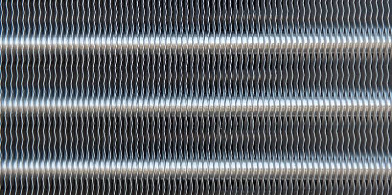
Since fins are a passive cooling method, they are used in a variety of applications ranging from engine cooling to electronics cooling. The most common places one would see fins is in an air-conditioning unit. The small, densely packed wavy-structures are fins rejecting heat to the surrounding in a refrigeration cycle.
 |
 |
 |
|---|---|---|
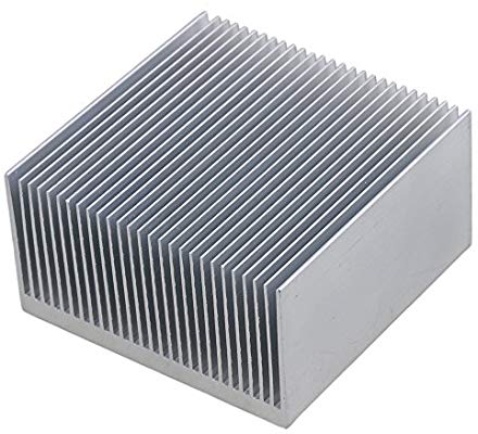
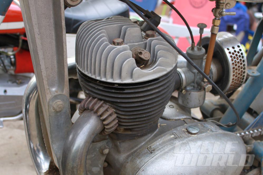
| Fins used for electronics cooling | The ridges and grooves that make up the cooling system of an engine are fins. | Condenser coil fins of an air-conditioning unit |
I was inspired to work on these systems when the updated MacBook Pro was released by Apple in 2016. The cooling system captured my imagination and I started thinking of way to improve the heat transferred from fins placed in a forced convection setting.
The idea for the novel designs came up from the flow around a golf ball. Golf balls are well-known to have dimples upon them, but nobody questions why they exist. It is a well-known, and a very contour-intuitive fact that golf balls travel further than a normal ball of the same size for the same impact. I always questioned this and my professor for Heat Transfers and Computational Fluid Dynamics, Professor Bagal explained the phenomena in great detail.
“Golf balls are a funny little thing”, he said. “The dimples on the golf ball create turbulence, which against intuition, reduces aerodynamic drag. On a smooth ball, the flow separates early. This creates a larger wake region behind the ball. In a dimpled ball, the air flow tends to stick to the surface due to the dimples. This creates a smaller wake region behind the ball. This reduces the aerodynamic drag.”
Drawing from this knowledge, I decided to apply this knowledge to the fins. From convective heat transfer, it was clear that creating a turbulent flow and/or creating a recirculating flow will improve heat transfer characteristics. And that’s what we did.
The Math and Physics Behind Fins
Before I jump into what we did, I wanted to draw attention to the physical and mathematical problem at hand.
A fin is a extended surface attached to a hot surface which assists in heat loss to the surrounding. Of course, the vice-versa is also true. From the above pictures, it is clear how a fin looks for in real-world applications. For a theoretical understanding of fins, I will try to show the fin and discuss the mathematics behind it. For the curious readers, I would recommend referring to the “Fundamentals of Heat and Mass Transfer” by Theodore L. Bergman and my academic advisor at UCLA, Adrienne S. Lavine.
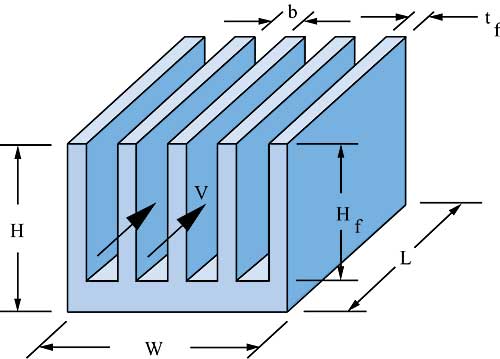 |
The above figure shows multiple fins. For the simplest design, consider only one fin, and assume that the fins do not interact with each other. The lower surface is assumed to be hotter than the surrounding (Tb > T∞). In its current form, the problem is in 3D. If we make simplifying assumptions of assuming a long, slender fin, we can reduce the problem down to 1D.
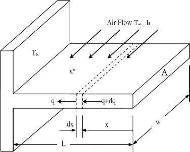 |
From analysis available in Fundamentals of Heat and Mass Transfer, the equation governing equation for the fin becomes:
\[ \dfrac{d^2\theta}{dx^2} - m^2\theta = 0 \] where \( m^2 = \dfrac{hP}{kA} \) and \( \theta = T - T_{\infty}\) with boundary conditions given by: \[ \theta(0) = T_b\] and either of:
-
Infinitely Long Fin: \( \theta(L) = 0\)
-
Prescribed Temperature: \( \theta(L) = \theta_L\)
-
Insulated Tip: \( \dfrac{d\theta}{dx}\Biggr\vert_{x=L} = 0\) or \( \dfrac{d\theta}{dx}\Biggr\vert_{x=L} = hA\theta(L)\)
The following results can be inferred from the respective boundary conditions:
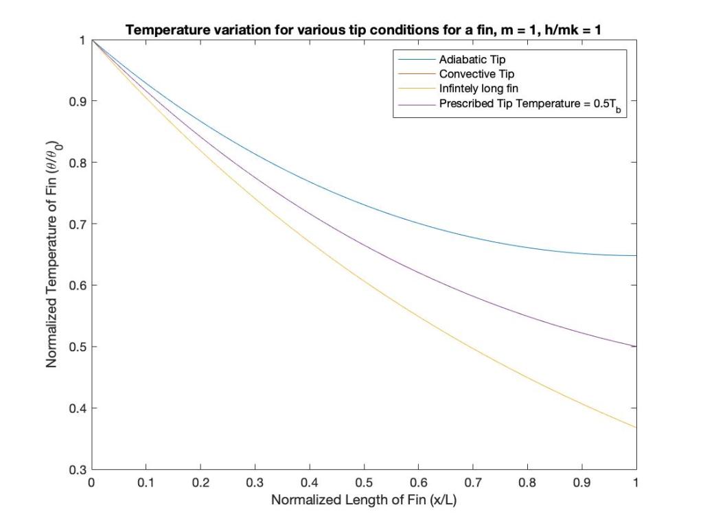
The mathematical solutions for each boundary condition can be obtained in Fundamentals of Heat and Mass Transfer.
Golf Balls and Fins
Inspired by the dimples and their ability to increase turbulence (and in turn, heat transferred), we chose to add differently shaped dimples to the surface of the fin. We selected spherical, ellipsoidal, cylindrical and pyramidal dimples for our experiments.
One way to make a quick inference of the results from our experiments was to prevent variation in exposed surface area. Mathematically,\( \dot{q} = hA\Delta T\) or \( \dot{q} \propto h\Delta T\) if \( A\) is constant. Now, if \( \dot{q} = constant\), \( h\Delta T\) must be a constant too. Now, we can safely say that \( h \propto \dfrac{1}{\Delta T}\).
Thus, we designed the fins such that the exposed surface area for each design was held constant. We ensured this by varying the depth of the dimples. While we could have varied the dimple print hydraulic diameter also, we chose this dimension to be a parameterizing dimension and kept it constant.
Now we had 4 dimpled fins with similar physical structures and dimensions except for the dimples on the surface of the fins.
Experimentation
For conducting experiments, we needed a controlled environment. To achieve this, we developed a custom wind tunnel. This wind tunnel allowed to us control the velocity of the air before the experimental piece. We also added flow straighteners to the wind tunnel to reduce the turbulence present in the flow which may have been introduced due to the fan.
The material for the fins was selected depending upon its thermal conductivity and machinability. We decided to go with aluminum because it was highly machinable, had excellent thermal conductivity, and was relatively cheap. Its paramagnetic nature also came as an added benefit as the project progressed (discussed next).
To heat the base of the fin, we used an induction cook-top that provided a constant 100W of power. Previously, we had thought of using Joule losses in nichrome wires to heat the aluminum. On preliminary iterations of the experimental set-up, we could not prevent exposed wires. This was deemed to be extremely dangerous when carrying 100W of power. Further, if the aluminum fin came in contact with the live wires, there would be further problems due to \[ I^2R\] losses in the aluminum. To prevent the problem of exposed wires while maintaining a certainty on power transferred, I suggested the use an induction cooktop.
The induction cooktop was an ingenious solution. Aluminum is a paramagnetic material, and thus is weakly affected by changing magnetic fields. Thus, we cannot have eddy current losses in the aluminum body of the fin. Now, to create a constant base heat flux, we put a thin flat iron plate which is ferromagnetic in nature. The eddy current heat losses could be accurately estimated and provided a constant heat flux to the base of the fin in the experimental setup.
Numerical Simulations
I designed the experimental setup and fins on SolidWorks for CFD simulations. The problem to solve was a classic conjugate heat transfer problem. Constant heat flux was added from the bottom of the fin. Heat was carried away by the colder fluid through forced convection. The simulations were conducted in a pressure-based solver using the SIMPLE method. To model turbulence, we used the two-equation \( k-\epsilon\) model.
The results of the simulation was studied and processed in Python. The temperature variations were used to validate the numerical simulations against the real-world experiments. The data showed good correlation with uncertainties under our threshold. The temperature variation was also used to determine the Nusselt Number ratio compared to the base case (without dimples). A graph was plotted for the variation of Nusselt Number across the length of the body for different heights on the fin.
Further, from data obtained from simulations, we could observe the flow around the dimples that enabled the heat transfer augmentation. This also gave us an understanding of how the shape of the dimple affects the degree by which heat transfer is increased.
Results and Conclusions
The data obtained from the experiments and numerical simulations confirmed our hypothesis. Adding dimples to the surface of a fin does increase heat transfer and this effect is not just because we have an increased exposed surface area. Flow circulation like the one seen on golf balls is responsible for the augmentation. The gently curved dimples (like the spherical and ellipsoidal dimples) provide a better heat transfer augmentation as compared to the sharper dimples (cylindrical and pyramidal dimples).
Personal Note
This was my first extensive research and I am extremely proud of my work. I fell in love with CFD during this time. I was also able to master my knowledge on heat transfer and fluid dynamics through this work. The learnings gained from the research have guided me in life and graduate school. I feel extremely grateful to Professor Bagal and my friends who were a part of this research.
This research is a part of the Proceedings of the International Mechanical Engineers Conference and Exposition hosted by ASME in 2018 in Pittsburgh, PA from November 9 to 15, 2018. The rights to the paper are owned by ASME. All of the above text is referenced to the paper “Heat Transfer Augmentation From Extended Surfaces Using Dimples”.